Introduction
Thank you for purchasing Super MIDI Pak! Super MIDI Pak is a cartridge that turns your SNES/SFC into a standard MIDI synthesizer. Here is a list of available features:
- Compatible with Super Famicom, NTSC/PAL Super Nintendo, and Super NT
- 16 polyphonic midi channels with independent settings multiplexing over 8 voices
- Standard MIDI sustain, sostenuto, legato switch, portamento (glide), pitch bend, vibrato, pan, volume
- High degree of GM (General MIDI) Level 1 and Level 2 compatibilty, including a complete GM patch set. Plays most GM MIDI files out of the box.
- Advanced MIDI features custom tunings, pitch bend sensitivity, master tuning.
- Pitch AD envelope, amplitude ADS envelope.
- MIDI mono mode (mode 4) with legato operation
- All SPC700 DSP registers are directly writable via CC messages, including echo registers
- New samples can be uploaded via WebMidi application (Windows/Mac/Linux), automatically converts from SPC/WAV/SF2 formats.
- Web application provides conversion from MIDI to SPC format (Beta).
- "Test mode" to allow triggering notes via the control pad
- USB Micro-B and 3.5" TRS Type A MIDI interfaces
- USB interface is galvanically isolated to prevent ground loop noise
- Save device settings across power off and reset
- Play existing SPC files
- Firmware upgradable
Getting Started
Super MIDI Pak conforms to the MIDI standard very carefully so you should be able to hook it up to your existing MIDI gear and get started immediately. If you are less familiar with MIDI this section will briefly acquaint you with how to hook it up.
Super MIDI Pak has three ports. A USB port and two 3.5" TRS ports. The USB port is provided to make it easy to connect Super MIDI Pak to your computer. USB cannot be used with another MIDI device unless it's a MIDI host, doing so may damage both devices. The two 3.5" TRS ports are MIDI ports that can be used with other MIDI devices, these are not audio ports. It's important to note that both the USB port and the pair of TRS ports provide equivalent functionality, everything you can do with the USB port can be done with the two TRS ports and vice versa. While it's safe, unless you know what you're doing, it's not recommended to have both the TRS ports and the USB port connected as they can interfere with each other.
Some MIDI devices may use traditional DIN MIDI ports instead of 3.5" TRS ports. To connect Super MIDI Pak to these devices you need to use a Type A 3.5" TRS to DIN adapter, such as this one.
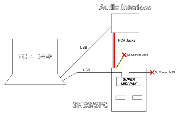
To get audio out of the SNES/SFC, you use the normal audio output from the multi-out connector. If you are recording audio from the SNES/SFC into an audio interface, avoid having the video simultaneously connected to a separate TV or monitor as this may cause ground loop noise into your audio interface.
Here is one example setup that you may use when sequencing your SNES/SFC from your computer:
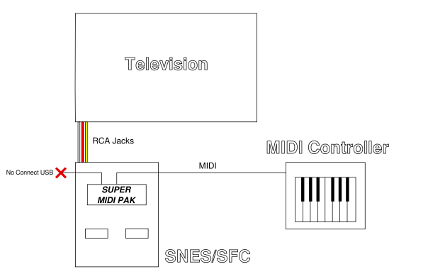
Here is another example that you may use when playing the Super MIDI Pak live from a MIDI controller:
If you plan on using Super MIDI Pak with your PC, you can test the setup by using a program like MidiEditor on Windows or APPlayMIDI on macOS to play pre-existing MIDI files on the device. Make sure that on Windows you have no other application open accesing the device, since Windows only allows a single application to access USB MIDI devices at a time.
Button Masher has put together a step-by-step video tutorial on how to use Super MIDI Pak to compose music from your computer.
Web Application
The web application is available at https://www.supermidipak.com/app. It provides easy access to the advanced features of Super MIDI pak, in particular converting and uploading custom samples.
Uploading Samples
The "Sample Uploader" page of the web application allows you to import and upload custom samples onto Super MIDI Pak.
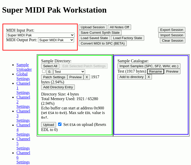
The right pane shows the "sample catalogue." This is the catalogue of all samples that have been imported into the web application. These samples are not uploaded to Super MIDI Pak, they are simply available to choose from when deciding which samples you want to actually upload. Samples must first be imported into the catalogue before they can be selected in the "sample directory." You can import samples by pressing the "Import Samples" button and selecting the source file. To remove a sample catalogue entry, select the "X" button.
The left pane shows the "sample directory." These are the samples that will actually be uploaded to Super MIDI Pak.
The numbers to the left of each entry specify the index of the directory entry. This is the value that should be used to select this sample when changing the program using the MIDI "Program Change" message. To change the index of the directory entry, just click the index number button and enter a new value.You can use the dropdown to select the specific sample that you'd like to occupy the directory entry. You may select any sample that you have imported into the sample catalogue.
You can edit the Volume ADSR and Pitch AD settings of each directory entry by selecting the corresponding "Patch Settings" button. These settings are automatically used by the channel when the program directory entry's program is selected on the channel, as long as CC#83 is disabled. You may also edit the patch settings of multiple directory entries at once by selecting the checkbox on the left of the desired directory entries and pressing the "Edit Selected Patch Settings" button.
To remove a sample directory entry, select the "X" button.
Once you are done setting up your desired sample directory, you can upload your samples by pressing the "Upload" button at the bottom of the pane. Be sure that the correct "MIDI Input Port" and "MIDI Output Port" have been selected at the top of the application. This takes approximately 30 seconds when using the entire SNES sample memory.
Web App MIDI Input
When managing Super MIDI Pak's settings using the the web application while also composing using your DAW or sequencer, you will quickly run into the issue of settings that you set in your DAW via MIDI CC events becoming out of sync with the settings that are contained in the web application. This can lead to confusing scenarios where you forget if your DAW or the web app has the authoritative settings. To deal with this issue, the web application exposes a MIDI input port to which you can connect your DAW. All MIDI messages sent to this port update the state of the web app and are also forwarded to Super MIDI pak (via the set MIDI Output Port).
You will find this setting near the other MIDI ports settings under the label "Web App MIDI Input Port." You can either create a virtual MIDI port in your OS and then assign the output of that virtual port to the "Web App MIDI Input Port," or you can select the output port of your DAW (if it exposes one).
Modulating the Web App's Band Pass Filter Generator
The web app contains a band pass filter generator in the "Echo
Settings" section. You simply provide a center frequency and a
filter width and the web app will compute the
best FIRx register values that reflect the given
parameters. You may want to modulate the filter generator
parameters in real-time from your DAW or MIDI sequencer. To
support this use case the web app maps CC#92 and CC#95 on its
input port to the center frequency and filter width parameters,
respectively. Be aware that these two specific MIDI messages are
not forwarded onto the MIDI output port.
The web app also contains a feedback-based band pass filter generator. Due to the limitations of the feedback machinery of the SPC700, the width of this filter is not configurable but there is a "resonance" setting which has a simultaneous effect on both the width of the peak but also the peak amplification. A resonance setting of 0 makes the peak amplification always 0dB. This filter can be preferable over the non-feedback-based band pass filter because it only has a single peak and no ripple in the magnitude plot. You can modulate the center frequency of the filter by sending CC#94 to the input port of the web app, you can modulate the resonance by sending CC#93 to the input port of the web app,
Sample Encoding Parameters
When importing sample files that must first be encoded into the SNES's compressed sample format (e.g. WAV files), the web application provides few parameters that may help you obtain better sounding samples.
Loop Duration
Loop duration is the length of time from the end of the sample to a point earlier in the sample that constitutes the looping portion of the sample. This parameter is specified in milliseconds. Due to the SNES's sample format, the loop duration can only be in increments of 0.5 ms, e.g. 0.5 ms, 1 ms, 1.5 ms, etc. A value of 0 means the sample does not loop.
Dither Seed
Since encoding to the SNES's sample format is a lossy process, some dither is usually required so that the encoded sample sounds as clean as possible. Dither is a small amount of random noise added to the sample before encoding to make the noise due to a reduced bit-depth sound like white noise instead of added harmonics. The exact stream of random noise that is added to the sample is fully defined by the "dither seed." You may find that some dither seeds work better than others, especially for harmonically poor samples (i.e. pure tones). A value of 1 is the default.
Dither Gain
The dither noise that is added to the sample has a power that is proportional to the lowest significant bit of a 16-bit sample. You can tweak the power of the dither noise by applying a gain to the dither, which is defined by this parameter. In certain cases more dither may sound better and in other cases less dither may sound better, but generally the default dither gain works well. This parameter is specified in bits. A value of 0 is the default.
Ensure Padded Sample
The SNES sample decoding process has two quirks. The first quirk is that the first 16 samples of a full sample must be encoded using the most lossy method, making it sound less than optimal. The other quirk is that the last 28 samples of a full sample are ignored. If you pad your sample with zeros at the beginning and end of your full sample you can avoid these quirks from impacting your sample. The downside is that this causes a 0.5 ms delay to your sample, so you may want to take that into account in your compositions. It also takes up a marginal amount of memory. If your samples are not sufficiently padded with zero samples at both ends, this option will ensure they are. If your samples are already sufficiently padded, then this option does nothing. By default this parameter is enabled.
Compensate for Interpolation
After sample decoding, the SNES passes the sample data through an interpolation filter as part of the pitch-shifting process. This interpolation filter has the effect of attenuating high-frequency components in your sample. There are two reasons for this:
- BRR encoding often adds some high frequency noise to the sample due to reducing the bit-depth and quantization noise.
- To pitch shift upward, frequency components above a certain cutoff must be completely attenuated to avoid aliasing. Since the SNES allows pitch shifting upward by a max of two octaves, this requires all frequency components above 4 KHz to be completely attenuated.
For samples that you don't intend to pitch-shift, e.g. drum samples, you may actually want to keep the high frequency components in your input sample. This parameter allows that by amplifying the high frequency components in your sample by the exact amount that they would be attenuated before encoding. By default this parameter is disabled.
Guaranteed Stable Looping
If the samples at the loop point happen to not use the most lossy encoding method, there is a chance that the looping will be unstable and corrupted if the samples prior to the loop point are not sufficiently equal to the samples at the end of the loop. To ensure stable looping we can force the BRR encoder to use the most lossy encoding method at the loop point. The downside is that you may hear slight noise each time your sample loops. It is recommended to make sure the 16 samples before your loop starts matches the end of the loop, rather than using this option. This option can come in handy when working with pre-existing samples or debugging your loop points. By default this parameter is disabled.
SPC Conversion Parameters
MIDI Source
This is the MIDI file that will be converted to SPC format.
Quantization
This is the minimum length of time between music events. Higher values reduce the SPC sequence size but the music may sound off rhythm. Leave at 0 to reduce quantization to a minimum.
Loop Point
This is the position from the beginning of the song in milliseconds to which the SPC will loop.
Artist Name
This is the artist name that will be put in the metadata of the SPC file.
Song Title
This is the song title that will be put in the metadata of the SPC file.
Factory Session
CosmicGem has provided the factory session for download. You can use this as a template when creating your own sample sessions.
Operation from Windows
Please note that Windows currently only allows a single application to access a MIDI device at a time. For example, if you are accessing Super MIDI Pak from the web application, you will not be able to use it from another Windows application. This is not a limitation of Super MIDI Pak, it is a limitation of Windows. Oftentimes you must quit the application using the device completely to free it, e.g. if Chrome has claimed the device you must quit Chrome entirely to allow your DAW to claim the device afterwards.
The simplest workaround is to use the Web App MIDI Input feature of the web app. Set the "Web App MIDI Input Port" to the output port of your DAW and then set the "MIDI Output Port" in the web app to the port that corresponds to Super MIDI Pak. This makes it so that only your browser is accessing the Super MIDI Pak device and your DAW is interacting with your browser.
Another possible workaround is to use the loopMIDI application to create a virtual MIDI port for each application that you plan to use concurrently with Super MIDI Pak. CosmicGem has provided a guide on how to use loopMIDI to workaround this limitation on Windows.
Echo System
The echo system is modified by
the EON, FLG, EVOLL, EVOLR, ESA, EDL,
EFB, FIR0, FIR1, FIR2, FIR3, FIR4, FIR5, FIR6,
and FIR7 registers. Here is a quick map of how they
are all interrelated
(source):
          ________                        _____                   _____
  c0 --->| ADD    |                      |MVOLc| Master Volume   |     |
  c1 --->| Output |--------------------->| MUL |---------------->|     |
  c2 --->| Mixing |                      |_____|                 |     |
  c3 --->|        |                       _____                  | ADD |--> c
  c4 --->|        |                      |EVOLc| Echo Volume     |     |
  c5 --->|        |   Feedback   .------>| MUL |---------------->|     |
  c6 --->|        |   Volume     |       |_____|                 |_____|
  c7 --->|________|    _____     |                      _________________
                      | EFB |    |                     |                 |
     EON  ________    | MUL |<---+---------------------|   Add FIR Sum   |
  c0 -:->|        |   |_____|                          |_________________|
  c1 -:->|        |      |                              _|_|_|_|_|_|_|_|_
  c2 -:->|        |      |                             |   MUL FIR7..0   |
  c3 -:->|        |      |         ESA=Addr, EDL=Len   |_7_6_5_4_3_2_1_0_|
  c4 -:->| ADD    |    __V__  FLG   _______________     _|_|_|_|_|_|_|_|_
  c5 -:->| Echo   |   |     | ECEN | Echo Buffer c |   | FIR Buffer c    |
  c6 -:->| Mixing |-->| ADD |--:-->|   RAM         |-->| (Hardware regs) |
  c7 -:->|________|   |_____|      |_______________|   |_________________|
                                   Newest --> Oldest    Newest --> Oldest
Super MIDI Pak does not interfere with these registers except in
a couple of cases.
CC#102 will cause Super MIDI Pak to
automatically modify EON to enable/disable
echo on voices triggered by the channel. Super MIDI Pak will
also not allow ESA/EDL
to overlap the first 256 bytes of the SPC700 memory. Any
writes to those registers that would cause the echo buffer to
overlap that memory space are undefined.
It is up to the user to select their desired echo parameters. A common echo setting to get started is:
EVOLL = 64(send 32 to CC#26)EVOLR = 64(send 32 to CC#27)EDL = 5(send 40 to CC#90)EFB = 60(send 30 to CC#9)FIR0 = 127(send 63 to CC#112)FIR1 = 0(send 0 to CC#105)FIR2 = 0(send 0 to CC#106)FIR3 = 0(send 0 to CC#107)FIR4 = 0(send 0 to CC#108)FIR5 = 0(send 0 to CC#109)FIR6 = 0(send 0 to CC#110)FIR7 = 0(send 0 to CC#111)
Drum Kit Mode
In Drum Kit Mode, Super MIDI Pak will choose the sample to play based on a direct mapping from note played to sample number. In this mode all program settings are ignored.
This mode can be used to create custom mappings from keys to samples. Potential applications include:
- Mapping an entire drum kit to a set of keys
- Multi-sample instruments, e.g. using different samples for lower and upper octaves to increase range / quality.
- Keyboard splits, i.e. one instrument on the left hand and another on the right hand.
See the section on Drum Kit Mode Switch NRPN#0 for more information on how to use this mode.
Test Mode
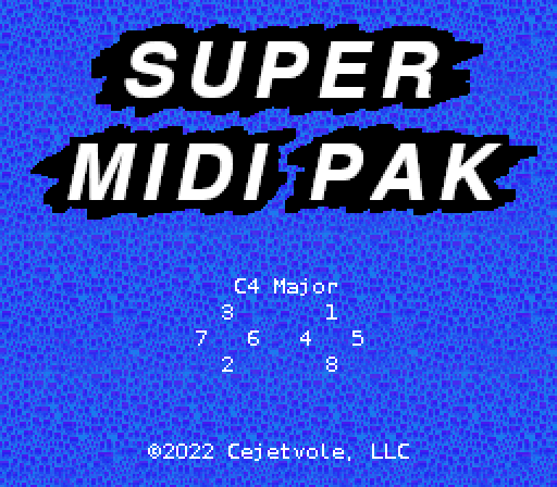
Super MIDI Pak includes a basic test mode that allows you to trigger notes with your SNES/SFC control pad. This mode is primarily intended for testing but can be used for performances as well.
To access this mode, hold down start and press the right shoulder button. This activates the menu. In the menu, select "Test Mode." Please note that while test mode is activated, the behavior of Super MIDI Pak in response to MIDI events coming in on channel 0 is undefined.
Basic Controls
In test mode, each d-pad direction and the four front-facing buttons, A, B, X, and Y map to a specific degree in a predefined scale. The mapping from button to scale degree was chosen to maximize the ease of playing the triads of the scale. The mapping is as follows:
| Button | Scale Degree | C Major (example) |
|---|---|---|
| X | 1 | C |
| Down | 2 | D |
| Up | 3 | E |
| Y | 4 | F |
| A | 5 | G |
| Right | 6 | A |
| Left | 7 | B |
| B | 8 | C |
Playing Accidentals
To pitch shift the currently playing notes up by a half step hold the left shoulder button. To pitch shift downward by a half step, hold the right shoulder button.
Changing Scales
To scroll through different scales, hold select and press either the X button or Y button.
Changing Key
To scroll through different keys, hold select and press either the left or right shoulder buttons.
Control Pad Keycombos
The following keycombos are permitted when Super MIDI Pak is at the title screen. They are designed to be easy to trigger even when no video output is connected to the system. They are also designed to be unlikely to be triggered accidentally, i.e. each keycombo requires a front-facing button to be held while pressing the Left and/or Right shoulder buttons.
Reset Unit to Factory Settings
Hold Select, Press Left Shoulder + Right Shoulder.
This clears the synth state that was saved with Save Settings #9 so that it powers on with default factory state. It also loads the default factory state.
Load Factory Settings
Hold Up, Press Left Shoulder + Right Shoulder.
This puts Super MIDI Pak into the default factory state but does not modify the settings that were saved with Save Settings #9.
Load Saved Settings
Hold Down, Press Left Shoulder + Right Shoulder.
This puts Super MIDI Pak into the exact state that was saved with Save Settings #9.
Increment Device ID
Hold Left, Press Right Shoulder.
This increments the device ID. Device ID dictates which SysEx messages the unit accepts and responds to. It is not recommended to change this except in advanced use cases.
Decrement Device ID
Hold Left, Press Left Shoulder.
This decrements the device ID. Device ID dictates which SysEx messages the unit accepts and responds to. It is not recommended to change this except in advanced use cases.
Reset Device ID
Hold Left, Press Left Shoulder + Right Shoulder.
This resets the device ID to 0. Device ID dictates which SysEx messages the unit accepts and responds to. It is not recommended to change this except in advanced use cases.
Increment Basic Channel
Hold Right, Press Right Shoulder.
This increments the basic channel. Basic Channel dictates which MIDI messages the unit accepts when omni mode is off. It is not recommended to change this except in advanced use cases.
Decrement Basic Channel
Hold Right, Press Left Shoulder.
This increments the basic channel. Basic Channel dictates which MIDI messages the unit accepts when omni mode is off. It is not recommended to change this except in advanced use cases.
Reset Basic Channel
Hold Right, Press Left Shoulder + Right Shoulder.
This resets the basic channel to channel 1, which is the first MIDI channel. Basic Channel dictates which MIDI messages the unit accepts when omni mode is off. It is not recommended to change this except in advanced use cases.
Controller Reference
Channel Voice Controllers
Vibrato CC#1
This CC controls the amplitude of the vibrato. At max value (127) the vibrato shifts the pitch by +-50 cents, with a total swing of 100 cents, i.e. 1 semitone. At min value, no vibrato can be detected. It works on a linear scale, i.e. at a value of 64, the vibrato shifts the pitch by +- 25 cents.
Portamento Time CC#5
This value multiplied by 128 and added to Portamento Time Fine CC#37 makes up the duration in milliseconds of a portamento note transition.
Data Entry MSB CC#6
This value multiplied by 128 and added to Data Entry LSB CC#38 make up the value to be set for the parameter specified by RPN LSB CC#100 and RPN MSB CC#101. See RPN Reference for more information.
Volume CC#7
At max value (127), no attenuation occurs, i.e. the channel is
at max volume. The min value (0) is special, infinite
attenuation occurs, i.e. the channel is silenced. The power of
the signal is attenuated according to this equation:
dB = 40 * log(volume / 127).
Pan CC#10
Pan maintains constant signal power. Min value (0) shifts all output to the left channel, max value (127) shifts all output to the right channel.
This setting only takes effect if CC#89 is disabled.
Expression CC#11
At max value (127), no attenuation occurs.
The min value (0) is special, infinite
attenuation occurs, i.e. the channel is silenced. The power of
the signal is attenuated according to this equation:
dB = 40 * log(expression / 127).
Left Balance CC#12
Left/Right Balance CCs are an alternative to
using Pan CC#10. These CCs map more
naturally to the DSP voice
registers VOLL and
VOLR, giving the musician
greater control over left/right levels. In particular, this
allows musicians to access negative amplitudes. The exact
mapping to
VOLL is as follows:
VOLL = ((Value * 2) - 128 + (Value_Fine >> 6)) * Volume_Velocity_Expression_Scalar
When all
of volume, expression,
and velocity are at their max value (127), then no scaling is
done, i.e.
Volume_Velocity_Expression_Scalar = 1.
A value of 64 results in silence, while min value (0) is maximum negative amplitude and max value (127) is maximum positive amplitude.
This setting only takes effect if CC#89 is enabled.
Right Balance CC#13
This CC functions similarly to Left Balance
CC#12 except it applies to the DSP voice
register VOLR.
This setting only takes effect if CC#89 is enabled.
Portamento Time Fine CC#37
Portamento Time CC#5 multiplied by 128 then added to this value makes up the duration in milliseconds of a portamento note transition.
Data Entry LSB CC#38
This value added to to 128 multiplied by Data Entry MSB CC#6 make up the value to be set for the parameter specified by RPN LSB CC#100 and RPN MSB CC#101. See RPN Reference for more information.
Left Balance Fine CC#44
This CC fine tunes Left Balance. In practice when it is >= 64
then 1 will be added to the scaled value set
in VOLL when a note is
triggered. See Left Balance CC#12 for more info.
This setting only takes effect if CC#89 is enabled.
Right Balance Fine CC#45
This is the same as Left Balance Fine CC#44 except it applies to the right audio channel.
This setting only takes effect if CC#89 is enabled.
Sustain Pedal CC#64
When this value is >= 64, sustain is active. That means that notes that are turned off while sustain is active are left on. When this value < 64, sustain is off.
Portamento Pedal CC#65
When this value is >= 64, portamento is enabled. This means that notes played legato will transition in a portamento fashion. When this value < 64, portamento is disabled.
Sostenuto Pedal CC#66
When this value becomes >= 64, sostenuto is activated. This means that all notes that are currently held will continue to be held once released. When this value becomes < 64, then all notes that were held due to sostenuto will be released.
Legato Pedal CC#68
When this value is >= 64, new notes will take over the last played still active note in a legato fashion. When this value is < 64, new notes are played according to the current poly or mono mode.
Note that notes played in a legato fashion will transition to the new pitch using portamento if it is enabled.
This pedal is primarily for live performance in polyphonic mode. It gives the musician the ability to temporarily play new notes in a legato fashion.
Vibrato Rate CC#76
At min value (0) vibrato oscillates at 1Hz, at mid value (64) the vibrato oscillates at 6.5Hz, at max value (127) vibrato oscillates at 15Hz. This CC is on logarithmic scale.
Attack Time CC#81
This CC chooses the attack time that the channel will use. At the min value (0), attack lasts for 0 milliseconds, at max value (127) attack lasts 4.1 seconds.
This setting only takes effect if CC#83 is enabled.
Decay Time CC#82
This CC chooses the decay time that the channel will use. At the min value (0), decay lasts for 37 milliseconds, at max value (127) decay lasts 1.2 seconds.
This setting only takes effect if CC#83 is enabled.
Use Channel Synth Parameters CC#83
When the value of this CC is >= 64 then the this channel will use CC#81, CC#82, CC#85, CC#86, NRPN#1, NRPN#2, and NRPN#3 for the Volume ADSR and Pitch AD settings, respectively. When the value of this CC < 64, then it will use the Volume ADSR and Pitch AD settings that are bundled with the current program.
Set this CC to >= 64 when you want to interactively design how a patch should sound.
Portamento Control CC#84
This CC specifies from which note the portamento should shift. It only applies to the next "Note On" message received on this channel and is reset afterward.
This has the extra effect that if a currently sounding voice is playing the note specified by this CC, then the new note will trigger without re-attacking in a legato fashion, even in polyphonic mode without the legato pedal enabled. This gives the player extra control over which currently sounding voice is used for a legato transition instead of just the most recently played voice.
Sustain Time CC#85
This CC chooses the sustain time that the channel will use. At the min value (0), sustain lasts for 18ms, at max value (127) sustain lasts forever.
This setting only takes effect if CC#83 is enabled.
Sustain Level CC#86
This CC chooses the sustain level that the channel will use. At the min value (0), the sustain level is 1/8 of the max envelope amplitude, at max value (127) the sustain level is the same as the max envelope amplitude.
This setting only takes effect if CC#83 is enabled.
Noise Frequency Slider CC#87
Noise frequency is typically controlled by
the FLG register but the bits
of that register are shared with other functions. This CC makes
changes only the noise frequency bits of that register, making
it convenient for using with a physical knob.
Use Left/Right Balance Pedal CC#89
This pedal decides whether to set relative left/right audio channels using the Pan CC or the Left/Right balance CCs. When it is <64 the Pan CC will be used to control left/right audio levels, when it is >=64 the Left/Right balance CCs will be used.
Echo Delay (EDL) CC#90
EDL is a 4-bit value while
MIDI CCs are 7-bit values,
This CC maps the CC range of values to the EDL range. Specifically
EDL will take on the value of this CC shifted to the right by 3 bits. This makes
it convenient to modify echo delay from a physical knob.
If you decrease EDL you must wait 300ms before increasing ESA, otherwise
the write to ESA results in undefined behavior. Setting EDL to a value that would result
in the first 256 bytes of SPC memory being overwritten is undefined.
NRPN LSB CC#98
This sets the LSB of the NRPN that is affected by Data Entry MSB CC#6, and Data Entry LSB CC#38. See NRPN Reference for more information.
NRPN MSB CC#99
This sets the MSB of the NRPN that is affected by Data Entry MSB CC#6, and Data Entry LSB CC#38. See NRPN Reference for more information.
RPN LSB CC#100
This sets the LSB of the RPN that is affected by Data Entry MSB CC#6, and Data Entry LSB CC#38. See RPN Reference for more information.
RPN MSB CC#101
This sets the MSB of the RPN that is affected by Data Entry MSB CC#6, and Data Entry LSB CC#38. See RPN Reference for more information.
Echo Pedal CC#102
When this value is >= 64, all notes played on this channel will be echoed. When this value < 64, all notes will not be echoed.
Noise Pedal CC#103
When this value is >= 64, all notes played on this channel will instead use the SPC700's white noise generation with no correspondence to the specific note played. When this value < 64, all notes will play as normal.
DSP Register Controllers
Super MIDI Pak maps all of the SPC700 DSP registers to MIDI CCs. This enables directly programming the SPC700 DSP without any interference from Super MIDI Pak's MIDI functionality. When MIDI running status is used, this allows a max throughput of approximately 1500 register writes per second.
Because the maximum number of data bits allowed by MIDI is 7 and all the SPC700 DSP registers are 8 bits wide, two MIDI CCs are allocated per register. The first CC multiplies the MIDI value by two and stores that as the register value. The second CC multiplies the MIDI value by two then adds one and stores that as the register value:
          Register = MIDI_CC_Value * 2
    if (is_second_cc) {
        Register = Register + 1
    }
The result of writing to these registers is out of the scope of this manual. Please consult an SNES/SFC programming guide to understand how modifying these registers affects sound production. One useful reference is the SFC Development Wiki.
Voice Registers
Each voice register can be written to by sending the corresponding CC to the channel that corresponds to the sum of the basic channel and the desired voice. For example, if the basic channel is channel 1 and you want to modify the register of the 2nd voice, then send the corresponding CC to channel 2.
Sending voice register CCs to channels past the 8th channel, starting at the basic channel, is undefined.
Channel Mode Messages
Reset All Controllers CC#121
This CC is primarily used to reset the state of all performance controllers and pedals of the channel. It is not intended as a way to reset the synth to a default state. It's useful after abruptly stopping a sequencer. Specifically for Super MIDI Pak it resets:
- Sustain is turned off (and all notes held by sustain)
- Sostenuto is turned off (and all notes held by sostenuto)
- Portamento Control CC#84 is reset
- Vibrato CC#1 is set to 0
- Expression CC#11 is set to 127
- NRPN and RPN parameters are set to null parameter (== 16383)
- Pitch bend is turned off (== 8192)
All Notes Off CC#123
This CC immediately sets all voices to the release stage of the envelope, exactly as if a "Note Off" message had been received for that voice. If sustain or sostenuto is active for that voice, the voice is held in sustain.
Omni Mode Off CC#124
By default Super MIDI Pak listens and reponds to messages on all 16 MIDI channels. To only listen to MIDI messages on the basic channel (often channel 1, the first channel), send this CC. In mono mode, it will listen to as many channels as requested, starting from the basic channel. Per the MIDI standard, this message causes an implicit "All Notes Off" command.
Omni Mode On CC#125
To get Super MIDI Pak back into a state where it listens to messages on all channels, send this CC. Per the MIDI standard, this message causes an implicit "All Notes Off" command.
Mono Mode On CC#126
By default Super MIDI Pak is in polyphonic mode. This means that multiple voices can play simultaneously. When in mono mode polyphony is restricted but exact operation depends on whether omni mode is enabled or not.
When omni mode is enabled, only a single voice can play simultaneously across all channels.
When omni mode is disabled, multiple channels are enabled and each channel is mapped to a voice. All channels are monophonic on their own but can play their respective voices in tandem. This mode is primarily intended for use with specific MIDI controllers, for example a guitar controller. In that example, each guitar string would be mapped to a different channel and only trigger at most once voice per channel.
The control value sent by this CC message, known
as M, tells Super MIDI Pak how many channels will
be active while in this mode and omni mode is disabled, starting at the basic channel (often
channel 1, the first channel). The value of 0 is special and
signals to activate as many channels as there are voices, which
for Super MIDI pak is 8.
Setting M to a value larger than 8 is undefined.
Sending MIDI messages to channels past the
Mth channel, starting at the basic channel, is undefined.
Mono mode results in legato transition between notes by default, as long as the consecutive "note on" is sent before the "note off" for the preceding note.
Per the MIDI standard, this message causes an implicit "All Notes Off" command.
Poly Mode On CC#127
This CC puts Super MIDI Pak back into default polyphonic state. Per the MIDI standard, this message causes an implicit "All Notes Off" command.
RPN Reference
RPNs are a standard way of specifying a large amount of synth parameters beyond what is possible using CC messages. They require multiple CC messages which make them slower than CCs.
To send an RPN you must first send the MSB of the specific RPN to CC#101, then the corresponding LSB to CC#100. Then send the MSB of the desired RPN value to CC#6, then the LSB of the desired RPN value to CC#38.
Pitch Bend Sensitivity RPN#0
To access this RPN, send 0 to CC#101 and then 0 to CC#100.
Behaves the same as in the MIDI standard. For example, a data entry value
of MSB=01 LSB=00 results in a pitch
bend range of +/- one semitone (a total range of two semitones)
for the channel.
Fine Tuning RPN#1
To access this RPN, send 0 to CC#101 and then 1 to CC#100.
Behaves the same as in the MIDI standard. More precisely,
the MSB and LSB of the data entry value result
in pitch shifting the channel by ((128 * MSB + LSB) - 8192) / 8192
semitones. For example, if MSB=65 and LSB=00,
the channel is shifted by (65 * 128 - 8192) / 8192 = 0.015625
semitones, which is 0.015625 * 100 = 1.5625 cents.
Course Tuning RPN#2
To access this RPN, send 0 to CC#101 and then 2 to CC#100.
Behaves the same as in the MIDI standard. More precisely,
the MSB of the data entry value results
in pitch shifting the channel by MSB - 64
semitones, LSB is ignored. For example, if MSB=65,
the channel is shifted by 65 - 64 = 1
semitone.
NRPN Reference
NRPNs are a standard way of specifying a large amount of propritary synth parameters beyond what is possible using CC messages. They require multiple CC messages which make them slower than CCs.
To send an NRPN you must first send the MSB of the specific NRPN to CC#99, then the corresponding LSB to CC#98. Then send the MSB of the desired NRPN value to CC#6, then the LSB of the desired NRPN value to CC#38.
Drum Kit Mode Switch NRPN#0
To access this NRPN, send 0 to CC#99 and then 0 to CC#98.
To enable Drum Kit Mode send a value of >= 8192 (MSB >= 64, LSB can be anything). When Drum Kit Mode is enabled, current Bank and Program settings are ignored, instead the sample played is 128 plus the MIDI value of the note triggered. E.g. when middle C is triggered (60), sample 188 in the sample directory is used.
Pitch Attack Time NRPN#1
To access this NRPN, send 0 to CC#99 and then 1 to CC#98.
This controls the amount of time that the attack phase of the pitch envelope takes to reach the max amount (chosen by Pitch Envelope Amount NRPN#3). When the MSB (top 7-bits) is 0, the attack phase is special cased to be 0 seconds, this allows the pitch envelope to start at the max amount and ramp down. At the value of 128 (MSB == 1), the attack phase is ~65ms. At max value (16383, MSB = 127) the attack phase is 12 seconds. The CC is on a logarithmic scale.
This setting only takes effect if CC#83 is enabled.
Pitch Decay Time NRPN#2
To access this NRPN, send 0 to CC#99 and then 2 to CC#98.
This controls the amount of time that the decay phase of the pitch envelope takes to reach zero from the max amount (chosen by Pitch Envelope Amount NRPN#3). At min value (0) the decay phase is 46.875ms, at max value (16383) the decay phase is 12 seconds. The CC is on a logarithmic scale.
This setting only takes effect if CC#83 is enabled.
Pitch Envelope Amount NRPN#3
To access this NRPN, send 0 to CC#99 and then 3 to CC#98.
This is the max amount that the pitch of a new note is shifted by the pitch envelope when it is triggered. A value of 8192 results in no shifting. A value of 16383 results in a max shift upward by 31.5 semitones, a value of 0 results in a max shift downward by 32 semitones.
This setting only takes effect if CC#83 is enabled.
Set Unavailable Voices NRPN#4
To access this NRPN, send 0 to CC#99 and then 4 to CC#98.
You can prevent the channel from using specific voices at "note on" with this NRPN. The format is a bitmask, when the corresponding bit is 1 that voice can not be used, when that bit is 0 then that voice can be used. E.g. if you send the value 255 (11111111 in binary) to this NRPN, that will prevent "note on" events from using any voices. If you send the value 0 to this NRPN, that will allow "note on" events to use any voice for this channel. If you send the value 165 (10100101 in binary), that will prevent the channel from using voices 0, 2, 5, and 7.
The default value is 0, that means the channel will be able to make use of any voice.
This NRPN is useful when you need more fine-grain control over how Super MIDI Pak allocates voices. This is particularly useful when composing music that will be converted into an SPC file.
MIDI Tuning SysEx Reference
Super MIDI Pak supports a subset of the MIDI Tuning standard which allows custom "microtunings" (user-defined scales other than the 12-tone equal temperament).
Single Note Tuning Change #2
This is a "real-time" SysEx message that specifies new frequencies for the specified MIDI notes. It takes place immediately. The format of this SysEx is as follows:
F0 7F <device ID> 08 02 00 ll [kk xx yy zz] ... F7
F0 7F |
Universal Real Time SysEx header |
<device ID> |
ID of target device, usually 0 |
08 02 |
MIDI Tuning Standard, Single Note Tuning Change code |
00 |
Tuning program number, must be 0 |
ll |
number of changes (1 change = 1 set of [kk xx yy zz]) |
kk |
MIDI key number |
xx yy zz |
New frequency, format described below |
F7 |
SysEx footer (EOX) |
Frequency Format
Frequencies are specified in terms of fractional semitones, where xx=69 yy=00 zz=00
corresponds to A440. Given a target frequency of f, the expressions to
compute xx yy zz are as below:
s = 12 * log(f / 440) / log(2) + 69
|
xx = floor(s)
|
yy = floor(s * 2 ^ 7) % (2 ^ 7) |
zz = floor(s * 2 ^ 14) % (2 ^ 7) |
SysEx Reference
Reset Complete #1
This SysEx is sent by Super MIDI Pak after it has finished initializing when it is powered on or reset. The format is as follows:
F0 00 02 3E <device ID> 00 01 F7
F0 00 02 3E |
SysEx header |
<device ID> |
ID of target device, usually 0 |
00 |
Product ID |
01 |
Reset Complete SysEx code |
F7 |
SysEx footer (EOX) |
Handshake #3
Handshake packets are intended to be used with long-running SysExs that require the user to pause sending MIDI events until a handshake SysEx is received over the ouput MIDI port, or predefined amount of time passes. This SysEx is generally received from Super MIDI Pak rather than sent to it.
The format of this SysEx is as follows:
F0 00 02 3E <device ID> 00 03 tt <packet index> F7
F0 00 02 3E |
SysEx header |
<device ID> |
ID of target device, usually 0 |
00 |
Product ID |
03 |
Handshake SysEx code |
tt |
Handshake code |
<packet index> |
Packet index from the initiating SysEx |
F7 |
SysEx footer (EOX) |
The different handshake codes and their meanings are summarized below:
| Name | Code | Meaning |
ACK |
7F |
Returned when the initiating SysEx completed successfully. |
NAK |
7E |
Returned when the data of the initiating SysEx was corrupted. User should resend initiating packet. |
CANCEL |
7D |
Returned when the initiating SysEx was incorrect, this usually indicates an erroneous client program. Resending will not fix the issue. |
WAIT |
7C |
Returned when the initiating SysEx may take longer than the predefined time to complete. User must
wait for a subsequent ACK, NAK, CANCEL, or FAILURE
Handshake SysEx.
|
FAILURE |
7B |
Returned when the unit encountered an error while trying to complete the SysEx. Retrying may or may not solve the problem. |
SPC Jump #6
This SysEx suspends normal operation of Super MIDI Pak and
instructs the SPC to start executing code at the specified
address. Before the SPC executes code, the specified values are
written to the APU0{0,1,2,3} registers on the CPU
side. Once any new MIDI message is received the custom SPC
program will halt and operation will continue as normal. Note
that Super MIDI Pak will not modify any SPC state once normal
operation is resumed, allowing the user to make use of the
leftover state, e.g. with DSP Jam Mode.
This SysEx is primarily intended to make it easy for users to run their own custom programs on the SPC. In particular it makes it easy to run existing SPC music files on Super MIDI Pak.
The format of this SysEx is as follows:
F0 00 02 3E <device ID> 00 06 aa bb cc dd ee ff gg F7
F0 00 02 3E |
SysEx header |
<device ID> |
ID of target device, usually 0 |
00 |
Product ID |
06 |
SPC Jump SysEx code |
aa bb cc dd ee ff gg |
7-bit encoding of [ ADDR_LOW, ADDR_HIGH, APU00, APU01, APU02, APU03 ] |
F7 |
SysEx footer (EOX) |
Save Settings #9
This SysEx causes Super MIDI Pak to save the current settings to internal memory. Please note that these settings will be loaded whenever the unit is powered on or reset. The settings include all channel settings, program settings, DSP registers, and SPC memory. The end result is that Super MIDI Pak will respond identically to MIDI messages when these settings are reloaded as when they were saved.
This SysEx is useful for when you are performing live or touring with Super MIDI Pak and need to minimize setup time.
This is a long-running SysEx. Do not send any MIDI messages after sending this SysEx until a Handshake message is received with the corresponding packet index. The format of this SysEx is as follows:
F0 00 02 3E <device ID> 00 09 <packet index> F7
F0 00 02 3E |
SysEx header |
<device ID> |
ID of target device, usually 0 |
00 |
Product ID |
09 |
Save Settings SysEx code |
<packet index> |
Packet index |
F7 |
SysEx footer (EOX) |
Load Saved Settings #10
This is the SysEx equivalent of the Load Saved Settings control pad keycombo. Unlike the control pad keycombo, the device ID is not altered. This is a long-running SysEx. Do not send any MIDI messages after sending this SysEx until a Handshake message is received with the corresponding packet index. The format of this SysEx is as follows:
F0 00 02 3E <device ID> 00 0A <packet index> 00 F7
F0 00 02 3E |
SysEx header |
<device ID> |
ID of target device, usually 0 |
00 |
Product ID |
0A |
Load Saved Settings SysEx code |
<packet index> |
Packet index |
00 |
Reserved, must be set to 0 |
F7 |
SysEx footer (EOX) |
Set Basic Channel #11
This SysEx allows the user to change the basic channel of the unit. The format of this SysEx is as follows:
F0 00 02 3E <device ID> 00 0B <basic channel> F7
F0 00 02 3E |
SysEx header |
<device ID> |
ID of target device, usually 0 |
00 |
Product ID |
0B |
Set Basic Channel SysEx code |
<basic channel> |
Desired basic channel of the unit. Operation is undefined if this is not in range of 0 to 15, inclusive. |
F7 |
SysEx footer (EOX) |
DSP Jam Mode Switch #14
This SysEx allows the user to prevent Super MIDI Pak from
modifying any register aside from KON,
KOFF, and P when handling the "Note
On" MIDI Message. This is useful when wanting to jam off the
leftover state of a custom SPC program that was run
using SPC Jump #6. In practice it often
makes sense to additionally disable omni mode and
enable mono mode.
The format of this SysEx is as follows:
F0 00 02 3E <device ID> 00 0D <enable DSP Jam Mode> F7
F0 00 02 3E |
SysEx header |
<device ID> |
ID of target device, usually 0 |
00 |
Product ID |
0D |
DSP Jam Mode Switch SysEx code |
<enable DSP Jam Mode> |
If this value is >= 64 then DSP Jam Mode will be enabled, it will be disabled otherwise |
F7 |
SysEx footer (EOX) |
Write SPC Memory #15
This SysEx allows the user to write to the memory of the SPC700. This is primarily intended for the user to upload custom samples but may also be used to upload custom programs to the SPC700, which can be run using the SPC Jump #6 SysEx.
Once the user sends this SysEx, they should not send any more MIDI events until either a Handshake SysEx is received on the output MIDI port or 100ms have passed. Doing otherwise will result in undefined behavior.
This SysEx can be used in either a "closed-loop" or "open-loop" configuration. An open-loop configuration is when the MIDI client is ignoring the output MIDI port of the Super MIDI Pak. In that case, the client should wait at least 100ms before sending subsequent MIDI events. This allows the user to include these SysExs in ".mid" files that can be played into the synth by a dumb player.
This SysEx can be sent while the synthesizer is normally operating. If timed correctly, this allows the user to dynamically swap out samples during a live performance.
All memory can be written except for the first 256 bytes of memory. Writes to that region are undefined.
The format of this SysEx is as follows:
F0 00 02 3E <device ID> 00 0F ii ll hh ss [ dd ] ... cc F7
F0 00 02 3E |
SysEx header |
<device ID> |
ID of target device, usually 0 |
00 |
Product ID |
0F |
Write SPC Memory SysEx code |
ii |
(SPC_TARGET_ADDRESS & 0x3) << 5) | PACKET_IDX |
ll |
(SPC_TARGET_ADDRESS >> 2) & 0x7f |
hh |
(SPC_TARGET_ADDRESS >> 9) & 0x7f |
ss |
Number of pre-encoded data bytes minus 1 |
dd |
A data byte, there will be ceil((ss + 1) * 8 / 7) of them. |
cc |
XOR checksum of all preceding bytes, not included initial 0xF0 |
F7 |
SysEx footer (EOX) |
If the checksum does not match, Super MIDI Pak will send
a NAK Handshake SysEx back over the MIDI output
port. Nothing will have been written. If it does match, Super
MIDI Pak will send an ACK Handshake SysEx back. If
Super MIDI Pak needs more time to process the data packet, it will
return a WAIT Handshake SysEx. In this case, the user should
not send any more data even if 100ms passes. The user should
wait for an ACK or NAK Handshake.
7-bit Data Encoding
Since the data bytes cannot have their high bit set, a conversion must happen to the source data before being transmitted over MIDI. A simple 7-bit encoding algorithm is used, For every group of 7 input bytes, the bottom bits are shifted out and are used to make up the bits of a "header" byte from the least significant bit to the most significant bit. Python-like pseudocode to do the encoding is presented below:
buffer = []
header_byte = 0
while True:
  input_byte = read_byte()
  if input_byte is None: # no more data to encode
    break

  header_byte = ((input_byte & 0x1) << 6) | (header_byte >> 1)
  buffer.append(input_byte >> 1)

  if len(buffer) == 7:
    write_byte(header_byte)
    for byt in buffer:
      write_byte(byt)
    buffer = []
    header_byte = 0

# write out left over data
if buffer:
  write_byte(header_byte >> (7 - len(buffer)))
  for byt in buffer:
    write_byte(byt)
For example, consider the following group of 7 bytes:
aaaaaaaA bbbbbbbB cccccccC dddddddD eeeeeeeE fffffffF gggggggG
You would send that over the MIDI interface as:
0GFEDCBA 0aaaaaaa 0bbbbbbb 0ccccccc 0ddddddd 0eeeeeee 0fffffff 0ggggggg
Set Sample Root Pitch #16, #17
This SysEx allows the user to set the root pitch associated with a sample. The root pitch is the fundamental pitch of the sample when it is played at normal rate, i.e. 32000Hz. This information enables Super MIDI Pak to set the correct pitch when a note is triggered with the "Note On" MIDI Message.
Since the DSP allows for 256 samples but only 128 different values
can be selected with a MIDI byte, two SysEx codes are allocated to this
function. The code 0x10 (16 in decimal) modifies the root pitch for
samples 0-127 and the code 0x11 (17 in decimal) modifies the root
pitch for samples 128-255.
The pitch format is the same as in the Single Note Tuning Change #2 SysEx. The format of this SysEx is as follows:
F0 00 02 3E <device ID> 00 <sysex code> <sample index> xx yy zz F7
F0 00 02 3E |
SysEx header |
<device ID> |
ID of target device, usually 0 |
00 |
Product ID |
<sysex code> |
Set Sample Root Pitch SysEx code. Use 0x10 for lower 128 samples, 0x11 for upper 128 samples. |
<sample index> |
Sample index. Added to 128 if SysEx code is 0x11. |
xx yy zz |
Desired root pitch, in MIDI Tuning Standard format |
F7 |
SysEx footer (EOX) |
Load Factory Settings #18
This is the SysEx equivalent of the Load Factory Settings control pad keycombo. Unlike the control pad keycombo, the device ID is not altered. It puts Super MIDI Pak into default factory state but it does not modify the settings that were saved with Save Settings #9. This is a long-running SysEx. Do not send any MIDI messages after sending this SysEx until a Handshake message is received with the corresponding packet index. The format of this SysEx is as follows:
F0 00 02 3E <device ID> 00 12 <packet index> 00 F7
F0 00 02 3E |
SysEx header |
<device ID> |
ID of target device, usually 0 |
00 |
Product ID |
12 |
Load Factory Settings SysEx code |
<packet index> |
Packet index |
00 |
Reserved, must be set to 0 |
F7 |
SysEx footer (EOX) |
Set Sample Volume ADSR #19, #20
This SysEx allows the user to change the default volume ADSR settings associated with a sample. These settings are used whenever the the channel is configured to use the sample synth parameters instead of the channel synth parameters.
Since the DSP allows for 256 samples but only 128 different
values can be selected with a MIDI byte, two SysEx codes are
allocated to this function. The code 0x13
(19 in decimal) modifies the volume ADSR settings
for samples 0-127 and the code 0x14
(20 in decimal) modifies the volume ADSR settings
for samples 128-255.
The meaning of the values used correspond exactly to the values used in CC#81, CC#82, CC#85, and CC#86. The format of this SysEx is as follows:
F0 00 02 3E <device ID> 00 <sysex code> <sample index> aa dd ll ss F7
F0 00 02 3E |
SysEx header |
<device ID> |
ID of target device, usually 0 |
00 |
Product ID |
<sysex code> |
Set Sample Volume ADSR SysEx code. Use 0x13 for lower 128 samples, 0x14 for upper 128 samples. |
<sample index> |
Sample index. Added to 128 if SysEx code is 0x14. |
aa |
Attack time value, same meaning as in CC#81. |
dd |
Decay time value, same meaning as in CC#81. |
ll |
Sustain level value, same meaning as in CC#86. |
ss |
Sustain time value, same meaning as in CC#85. |
F7 |
SysEx footer (EOX) |
Set Sample Pitch AD #21, #22
This SysEx allows the user to change the default pitch AD settings associated with a sample. These settings are used whenever the the channel is configured to use the sample synth parameters instead of the channel synth parameters.
Since the DSP allows for 256 samples but only 128 different
values can be selected with a MIDI byte, two SysEx codes are
allocated to this function. The code 0x15
(21 in decimal) modifies the volume ADSR settings
for samples 0-127 and the code 0x16
(22 in decimal) modifies the volume ADSR settings
for samples 128-255.
The meaning of the values used correspond exactly to the MSB values used in NRPN#1, NRPN#2, and NRPN#3. The format of this SysEx is as follows:
F0 00 02 3E <device ID> 00 <sysex code> <sample index> aa dd mm 00 00 F7
F0 00 02 3E |
SysEx header |
<device ID> |
ID of target device, usually 0 |
00 |
Product ID |
<sysex code> |
Set Sample Pitch AD SysEx code. Use 0x15 for lower 128 samples, 0x16 for upper 128 samples. |
<sample index> |
Sample index. Added to 128 if SysEx code is 0x16. |
aa |
Attack time value, same meaning as MSB in NRPN#1. |
dd |
Decay time value, same meaning as MSB in NRPN#2. |
mm |
Envelope amount value, same meaning as MSB in NRPN#3. |
00 00 |
Reserved bytes, must be 0 |
F7 |
SysEx footer (EOX) |
Troubleshooting
Super MIDI Pak Doesn't Show up in Web Application
You should only expect to see "Super MIDI Pak" as an option for the MIDI input and output ports in the web application if you have it connected to your computer over USB. If you are connecting it over an auxiliary MIDI interface, then the name of your interface should show up as an option in the input / output ports.
If you don't see "Super MIDI Pak" as an option for the MIDI input and output ports in the web application after plugging it in over USB, there are a couple of potential reasons why. Either the USB connection is bad or, if you are on Windows, then another application has already claimed the device.
Many USB Micro-B cables are charging-only cables so if your computer is not detecting Super MIDI Pak this is the most likely reason. It's also possible that a normal cable is too low quality. Try a high quality USB cable that you know is intended to carry data.
Timeout Error in Web App
Timeout errors occur when your MIDI input and output ports in the web application are configured incorrectly. The input and output ports must point to the MIDI interface over which your Super MIDI Pak is connected.
If both options are set to "Super MIDI Pak" and you are still seeing timeout errors, it's been reported that a few PC USB ports don' behave correctly with Super MIDI Pak. In that case, select the "Use without input port" option for the input port and try again.